HOW TO CLEAN THE EYEPIECE
Wrap
a sheet of lens tissue around a cotton swab as illustrated. If the area to be
cleaned is large, wrap the lens tissue looser and thicker. Otherwise, make a
thin, tight wrap.
Dip
the wrapped lens tissue in the cleaning solution, and wipe the eyepiece from
the center towards the periphery in a circular motion.
1) Never
rub the lens surface strongly.
2) Do not use the same lens tissue to clean more than one lens.
3) Do not moisten the lens tissue with an excessive amount of cleaning solution.
4) When cleaning with tweezers, be careful not to protrude its tip from the lens tissue.
2) Do not use the same lens tissue to clean more than one lens.
3) Do not moisten the lens tissue with an excessive amount of cleaning solution.
4) When cleaning with tweezers, be careful not to protrude its tip from the lens tissue.

Preparing for Inspection
1) Set
the main switch “A” to “I” (ON).
2) Adjust the brightness by turning the adjustment knob “B” .
3) Place a specimen on the stage.
4) Engage the 10X objective in the light path.
5) Rotate the condenser height adjustment knob ”C” to move the condenser to the highest position.
* The condenser is usually used in the highest position. If the entire observed field of view is not bright enough, brightness may be improved by lowering the condenser slightly.
6) Looking through the eyepiece in the right sleeve without the diopter adjustment ring, turn the coarse and fine focus adjustment knobs “D” to bring the specimen into focus.
7) Looking through the eyepiece in the left sleeve with the diopter adjustment ring, turn only the diopter adjustment ring “E” to focus on the specimen.
(At this time, adjust the interpupillary distance so that the binocular visions on the left and right fields of view coincide completely.)
8) Adjust the aperture iris diaphragm;
Since the aperture irirs diaphragm has an objective magnification scale (4X, 10X, 40X,100X), rotate the diaphragm ring “F” so that the magnification scale corresponding to the objective in use faces frontward.

Checking Dirty Portion
Image
influence caused by dirt on each component
The following figure shows the influence of image on each optical component if stains or dust is adhered to that portion.
In general, the microscope image is largely affected by dirt adhered on the nearer portion to a specimen and image surfaces.
Therefore, the optical components should be kept clean and dust-free.

A
Dirt is clearly seen.
B: Blurred contours of dirt is seen.
C: Dirt is seen when the aperture iris diaphragm is stopped down.
D: Dirt is not directly seen, but contrast of image deteriorates
B: Blurred contours of dirt is seen.
C: Dirt is seen when the aperture iris diaphragm is stopped down.
D: Dirt is not directly seen, but contrast of image deteriorates
How to find dirty portion through observation
1) Close the aperture iris diaphragm.
(When the aperture iris diaphragm is closed, it facilitates finding the dirt particles because the depth of focus increases and the dirt position bring into focus. However, very small dirt particle may not be found in this method.)
2) Observe a specimen through the eyepiece.
If dirt is seen by observing it, look for the portion where stains or dust is adhered by following the description below.
Note:
If dirty portion cannot be identified in the above, it is assumed that internal
lens and prism are contaminated. In this
case, please contact your Authorized dealer.

How to check cleaning condition
1) When a large lens is checked, look at the lens while putting it toward bright side or breathe on the lens and observe the condition that the haze on the whole surface of the lens disappears evenly.
1) When a large lens is checked, look at the lens while putting it toward bright side or breathe on the lens and observe the condition that the haze on the whole surface of the lens disappears evenly.
2)
For a small lens such as top lens of objective, check it by magnifier.

Optical Adjustment


Mechanical Adjustment
If
a specimen image is moved when the stage is brought into the desired position
of specimen, it is necessary to adjust the wire tension of stage.

Adjustment method for the tension of X-wire

Final adjustment
Image
backlash adjustment:
1) Under observation state (with 100X objective), move the stage to the desired image position by turning the Y-knob (A).
At that stop position, check image backlash.
If it is over 2 microns, conduct the following adjustment.
2) When adjusting the Y-movement, loosen the two screws (*1) and turn the Y-knob (A) to bring backlash within 2 microns.
* After turning the knob and temporarily tighten the screws, check image backlash in the observation state. Repeat the adjustment until image backlash is within the standard.
Screws: AWU3X4SA (*1) 2pcs.
3) For the X-movement, adjust image backlash by turning the X-knob (B) and check it in the same manner as the Y-knob.
Screws: AWU3X4SA (*2) 2pcs.
* The tension of X/Y knob becomes heavy or light by turning the knob as following direction.

Replacing Grease for Coarse/fine Adjustment Knob Ass’y
If the coarse/fine adjustment knob is not turned smoothly, replace greases on the portions described below.
(In case where the coarse adjustment knob is not turned evenly or the stage cannot be moved vertically, please contact your Authorized Olympus dealer because it is necessary to disassemble the left coarse adjustment knob (F) with shaft and/or guide unit.)
< Disassembling coarse/ fine adjustment knob>
1) Remove the fine adj. knob ass’y (A) and fine adj. knob (B) by turning them in arrow directions. (In fine adj. knob ass’y, the left fine adj. knob is fixed to the shaft with adhesive,OT1006)
2) Remove the spring washer (C) and washer (D).
3) Remove the fine shaft mount (E) with a spanner while holding the coarse adj. knob (F).
4) Remove the coarse adj. knob (G) by turning it counterclockwise while holding the coarse adj. knob (F).
5) Remove the tension knob (H) by turning it counterclockwise. (The washer (I) is attached to tension knob (H) with grease.)
6) Pull out the tension ring (J) while holding the convex part using a pliers.
7) Reassemble them in the reverse order.
(For applied portions of greases, refer to the figure on the right below.)

Replacing the Circuit Board
If
the lamp is not lit, check if the halogen bulb (6V20W) is broken or lamp socket
is burned and also check that the voltage is being outputted each from (1),
(2), (3) using multimeter to identify the defective part. (Refer to the figure
below.)
In
case where there is a problem in the circuit board, replace the circuit board
as a whole because the components can not be supplied. Since the rheostat ass’y
is incorporated in the circuit board,
the
voltage adjustment is not necessary. ( It has been already adjusted: Min. 1.5V
or less, Max. 4.5V +/-0.3 )
Replacement of circuit board / socket

Replacing
Pinion Ass’y of Plane Stage
(1) Loosen
the stopper (A) and remove the condenser (B) downward by turning Screws :
AB3X8SA, 2pcs. (*1) the knob (F).
(2) Remove the left dovetail (C) as seen from the front side.
(3) Remove the right dovetail (D).
Screws : AB3X8SA, 2pcs. (*2)
(4) Remove the pinion spring (E).
(5) Remove the pinion ass’y (F).
(6) Assemble the reverse order of disassembly.
(3) Remove the right dovetail (D).
Screws : AB3X8SA, 2pcs. (*2)
(4) Remove the pinion spring (E).
(5) Remove the pinion ass’y (F).
(6) Assemble the reverse order of disassembly.
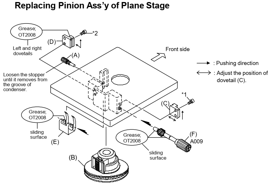
Note on assembly
Apply
grease to the portions shown as the above figure.
2) The right dovetail (D) is mounted by pushing it in the arrow directions.
3) The left dovetail (C) is mounted by pushing it in the upward direction.
At this time, adjust the position of dovetail (C) in the left and right directions so that the condenser moves smoothly without a play (vertical movement)


